The Computer Network Management course at HDU is too shallow. This article simply documents knowledge I have not learned yet during review.
The following sections are based on the course textbook “计算机网络管理(第三版)-西安电子科技大学出版社”.
Chapter 1 - Introduction to Network Manager
RFC Document
An RFC (Request for Comments) document is a technical standard or protocol published by the Internet Engineering Task Force (IETF). It defines fundamental internet specifications like HTTP, TCP/IP, and DNS. Each RFC has a unique number (e.g., RFC 791 defines the IP protocol). These documents serve as essential references for network engineers and developers.
Chapter 2 - Abstract Syntax Notation
ASN.1
ASN.1 (Abstract Syntax Notation One) is an international standard that defines how to represnet, encode, and transmit network data.
Think of it as a “universal language manual” for data. For example, when phones share files, without standardized rules, an Android device might send photos that an iPhone can not open. ASN.1 pre-defines rules like “photos must be sent in JPEG format, filenames encode in UTF-8.” This ensures all devices pack and unpack data the same – just like everyone speaking the same language for smooth communication.
Real-world applications include digital certificates for web authentication and monitoring data transmitted by routers, all relying on ASN.1 for standardized formatting.
Lexical Conventions
- Formatting is insignificant –multiple spaces or blank lines are equivalent to a single space.
- Identifiers (for values and fields), type references (type names), and module names consist of letters (case-sensitve), digits, and hyphens.
- Identifiers must start with a lowercase letter.
- Type references and module names must start with an uppercase letter.
- All ASN.1 built-in types are written in uppercase.
- Keywords are always in uppercase.
- Comments start with a double hyphen (
--) and end with another double hyphen or the line’s end.
Abstract Data Types
ASN.1 is a specification for describing data representation, encoding, transmission, and decoding formats.
ASN.1 tags are divided into four categories:
UNIVERSALTags: Defined by the standard, these are fundamental tags applicable in all scenarios. Basic types likeBOOLEAN,INTEGER, etc, use these by default.ApplicationTags: Used for a custom data types in specific applications, allowing protocols to define unique identifiers for their data structures.- Context-Specific Tags: Limited to local scope (e.g., within a complex structure like
SEQUENCE), trmporarily distinguishing fields within that context. PRIVATETags: Defined by users or organizations for internet protocols, assigning unique identifiers to proprietary data types.
ASN.1 defines over 20 data types, categorized into four groups:
- Simple Types: “Atomic types” consisting of a single component (e.g.,
BOOLEAN,INTEGER,BIT STRING). They define basic value sets and serve as building blocks for complex types. - Constructed Types: Composed of multiple elements (e.g., SEQUENCE—ordered field sets, SET—unordered with unique fields). They build complex data structures.
- Tagged Types: Derived from existing types using explicit/implicit tags, enabling type reuse and differentiation for flexible definitions.
- Other Types: Includes
CHOICE(select one from predefined types) andANY(matches any type—flexible but requires caution to avoid parsing ambiguity). These address special data description needs.
Macro Definitions
Macro Definitions are advanced features in ASN.1 that allow users to create reusable custom templates, simplifying the definitions of complex types.
Macros function like functions or templates in programming languages, but operate ar the type system level. They commonly used to defines sets of types with similar structures but varying details, such protocol message familirs or data reords formats.
Module Definition
The module in ASN.1 is similar to a structure in the C language and is used to define an abstract data type. A defined module can be referenced by name. For example, a module defines an abstract syntax, and an application entity sends the module name to the presentation service to specify the format of its APDU. The basic form of a module definition is as follows:
1 | <modulereference> DEFINITIONS ::= |
modulereferenceis the module name, followed by an optional corresponding object identifier.EXPORTSconstruct specifies the parts that the module can make available externally.IMPORTSconstruct specifies other types and values that the module needs to reference.AssignmentListpart contains all the type, value, and macro definitions of the module,
Here is an example of a module definition:
1 | LanNetworkModule{iso org dod internet private enterprises Xenterprises 95} |
Above ASN.1 module defines an abstract representation of Local Area Network (LAN) architectures. It primrily serves fot standardized description of LAN components in network management or communication protocols.
OID
In LanNetworkModule{iso org dod internet private enterprises Xenterprises 95}, the OID is iso org dod internet private enterprises Xenterprises 95. Its meaning and purpose are as follows:
An OID is a hierarchical, globally unique identifier resembling a “numeric address” that locates specific objects through its tree structure. The above OID can be broken down as:
iso (International Organization for Standardization) → org (organization branch) → dod (U.S. Department of Defense) → internet (internet branch) → private (private enterprises) → enterprises (generic enterprise branch) → Xenterprises (specific company name) → 95 (sub-branch assigned by the company).
Its numeric representation is: 1.3.6.1.4.1.95
where
iso=1,org=3,dod=6,internet=1,private=4,enterprises=1, andXenterprisesis assigned number95.
Macro Notation
ASN.1 macro notation is a mechanism for defining reusable “type templates”.
The core idea is to use macros to quickly generate similar ASN.1 types. It consists of macro definition (specifying the template structure) and macro instance (filling the template to get a specific type).
1 | -- Macro Definition: Specify the “template” for type and value |
Here is an example of a macro notation:
1 | -- Macro Definition: Create an “integer pair” template, specifying the type as SEQUENCE(INTEGER, INTEGER) |
When repeatedly using similar types (e.g., integer pairs, string pairs), macros let you define a template once and reuse it in instances – reducing code duplication and improving maintainability. This works like “function/class templates” in programming languages.
Basic Encoding Rule
Basic Encoding Rules (BER) encode abstract type values in ASN.1 as byte strings. The structure of these byte strings follows Type-Length-Value (TLV) format.
Chapter3 - Management Information Base
TCP/IP Protocol Suite
ARPANET: The precursor to the modern internet, it laid the groundwork for internet development and drove early network technology exploration.
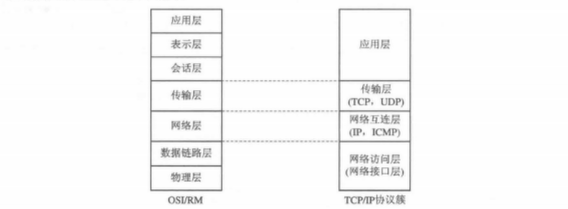
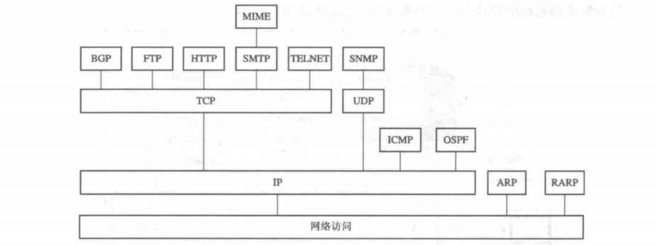
TCP/IP Protocol Suite: The foundational protocol set for internet communication, it defines rules for device interaction across multiple layers, from the application layer to the network interface layer.
SNMP (Simple Network Management Protocol): A TCP/IP-based network management protocol used to monitor and manage devices (e.g., routers, switches) and collect network data.
OSI/RM (Open Systems Interconnection Reference Model): A network architecture model by ISO, dividing communication into seven layers (application, presentation, session, transport, network, data link, physical) to standardize and explain network processes.
SNMP manages the operation of the TCP/IP protocol. Information related to the TCP/IP protocol’s operation is stored in the Management Information Base (MIB) using the structure defined by SNMP.
TCP/IP Network Management Framework
The following diagram illustrates the overall SNMP framework:
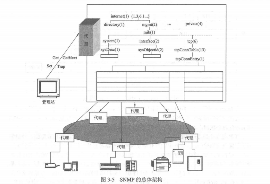
The upper part of the diagram shows the service primitives supported by the SNMP protocol. These primitives facilitate communication between the manager and the agent to query and modify the Management Information Base.
- Get retrieves data.
- Set modifies data.
- GetNext scans the MIB tree and retrieves data sequentially.
- Trap enables asynchronous reporting from the agent to the manager.
Trap - Directed Polling
To enable the management station to monitor managed devices timely and effectively without overly increasing network traffic load, a trap - directed polling process is used. Here’s how it works:
- Initial Polling Phase
When the management station starts or at fixed intervals, it uses Get operations to poll all agents. This fetches key info (e.g., interface characteristics) and basic performance stats (e.g., packet counts sent/received via an interface over time). After getting these baseline data, the management station stops polling. - Exception Reporting Phase
Agents then take over monitoring. When abnormal events occur (e.g., agent restart, link failure, load exceeding thresholds), the agent uses a Trap operation to actively report to the management station. This avoids continuous polling - induced network overload. - In - depth Event Query Phase
Upon receiving a trap, the management station can query the relevant agent (via Get operations again) for detailed info. This helps analyze root causes, forming a “baseline polling → active exception reporting → on - demand in - depth query” loop.
The Components of SNMPv1
The initial network management framework of the Internet was defined by four documents, which form the core of SNMPv1:
- RFC 1155 defines the Structure of Management Information (SMI), specifying the syntax and semantics of managed objects, establishing fundamental rules for describing management data.
- RFC 1212 explains how to define MIB modules, providing guidelines for standardizing the structure of Management Information Base modules.
- RFC 1213 defines the core set of MIB-II managed objects, which are essential for any SNMP system to implement.
- RFC 1157 serves as the protocol specification for SNMPv1, detailing its workflow and interaction logic.
MIB Structure
The MIB (Management Information Base) is a logical database storing management object information in network management, serving as the core component of SNMP (Simple Network Management Protocol).
It provides a standardized framework for information interaction between Network Management Systems (NMS) and Agents, allowing management stations to query or set object values via SNMP for network device monitoring and management.
Chapter4 - Simple Network Management Protocol
History of SNMP
SNMPv1
SNMPv1 was developed during the early days of the internet to provide a unified management solution for heterogeneous network environments. It uses a request-response model and relies on Get, Set, and Trap operations for data exchange between management stations and agents.
However, as a pioneering version, SNMPv1 has significant flaws:
- No security mechanisms – Data is transmitted in plaintext, with no authentication or encryption, making configurations vulnerable to tampering and information easy to steal.
- Limited performance – It supports only a few basic operations and struggles with large-scale data retrieval, making it inefficient for complex network management.
S-SNMP & SMP
To address SNMPv1’s security flaws, S-SNMP (Simple Secure Network Management Protocol) and SMP (Simple Management Protocol) emerged.
S-SNMP attempted to introduce MD5-based authentication and DES encryption to secure data transmission at its core. SMP focused on symmetric key authentication, aiming to verify trusted identities through key management mechanisms.
Unfortunately, both solutions failed to gain widespread adoption due to poor compatibility and lack of standardization, remaining experimental. However, they provided valuable insights for future protocol improvements.
SNMPv2
The emergence of SNMPv2 marked a major step forward in network management protocols.
On the functional side, it introduced the GetBulk operation, enabling bulk data retrieval and significantly reducing polling overhead. The InformRequest operation addressed the unreliability of traps by using acknowledgment mechanisms to ensure critical alerts were never lost.
For data types, SNMPv2 added new options like Counter64 to better handle traffic statistics in high-speed networks.
Security-wise, early versions still relied on community string authentication, but SNMPv2c later separated read-only and read-write permissions, reducing the risk of configuration tampering.
Compared to its predecessor, SNMPv2 not only improved management efficiency but also set the stage for future advancements with gradual security enhancements. This progress laid a solid foundation for the eventual maturity of SNMPv3.
Because SNMPv2 failed to meet commercial-grade security requirements – such as data origin authentication, high-level management capabilities and so on – the SNMPv3 working group continued developing a new standard.
Finally, in 1999, they released the SNMPv3 standard, addressing these critical security gaps.
SNMPv1
SNMPv1 Supported Operations
SNMP supports basic operations like retrieving and modifying the values of managed objects. Specifically, an SNMP entity can perform the following actions on objects in MIB-2:
- Get: Retrieves the value of a scalar object from the Management Information Base (MIB).
- Set: Modifies the value of a scalar object in the MIB.
- Trap: Allows an agent to notify the manager of changes in managed object states using trap messages.
However, SNMP does not permit managers to alter the structure of the MIB—meaning they cannot add or delete instances of managed objects (e.g., adding or removing table rows).
SNMP PDU
To understand how SNMP transfers data between devices, first break down its message and PDU (Protocol Data Unit).
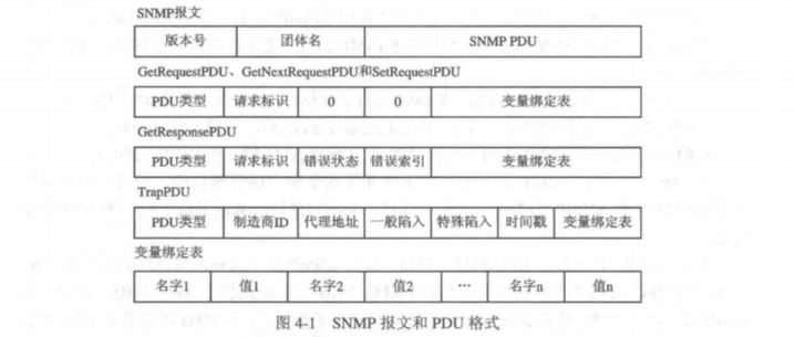
An SNMP message has a “three-layer” structure: version number, community name, and SNMP PDU.
- The version number indicates the SNMP version (e.g., SNMPv1).
- The community name acts like a simple password—the agent and manager must use the same one, but it is transmitted in plaintext, making it insecure.
- The most critical part is the SNMP PDU, which contains the actual operation details.
SNMP defines 5 management operations, but the Request PDUs (3 types) from the Manager.
Request PDUs (3 types) from the Manager
GetRequest, GetNextRequest, and SetRequest share the same PDU structure:
1 | PDU Type + Request ID + 0 + 0 + Variable Bindings |
- PDU Type: Numeric code to distinguish operations (e.g., 0 for GetRequest, 1 for GetNextRequest).
- Request ID: Unique identifier assigned by the manager. The agent echoes this in the response to match requests with replies and prevent duplicate packets (e.g., from network retransmissions).
- Variable Bindings: List of MIB objects to operate on. For Get requests, specify the target OIDs; for Set requests, include OIDs and their new values.
Response PDU (1 type) from the Agent
The agent uses GetResponsePDU for all replies (Get, GetNext, or Set), with the structure:
1 | PDU Type + Request ID + Error Status + Error Index + Variable Bindings |
- Error Status: Result code (e.g., noError for success, tooBig if response exceeds size limits, noSuchName for invalid OIDs).
- Error Index: If an error occurs (non-zero Error Status), this points to the problematic variable in the binding list for troubleshooting.
Trap PDU (1 type) from the Agent
Traps are unsolicited alerts sent by the agent. Their format differs significantly:
1 | PDU Type + Enterprise ID + Agent Address + Generic Trap + Specific Trap + Timestamp + Variable Bindings |
- Enterprise ID: Matches
sysObjectIDin MIB-2, identifying the vendor (e.g., Huawei or Cisco). - Agent Address: IP of the device sending the trap (“who is reporting”).
- Generic Trap: Standard alert type (e.g., coldStart for reboots, linkDown for broken links).
- Specific Trap: Vendor-defined alert codes, varying by device.
- Timestamp: Time the trap was sent (sysUpTime in MIB-2), indicating “when the event occurred.”
Chapter5 - Remote Network Monitor
Firstly, let us learn what is RMON!
I suddenly realized I haven’t explained what MIB-2 is!
MIB-2 is the standardized second-generation implementation of MIB. It clearly classifies and defines objects within the MIB, serving as a “standard version” in the evolution of Management Information Bases.
What is RMON
RMON (Remote Network Monitoring) is a network management standard based on the SNMP framework, specifically designed to monitor data traffic on network segments or entire networks.
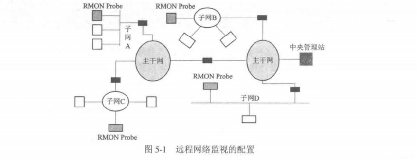
It was initially developed to manage multiple LANs and remote sites from a central point, improving network management efficiency. The core concept involves storing network information in the RMON MIB (Management Information Base). Probes (agents/monitors, which can be embedded in routers, switches, or run as PC programs) collect data, while management stations retrieve this data using SNMP for network monitoring.
RMON has two widely used versions:
RMON v1: Widely adopted, it defines 9 MIB groups (statistics, history, alarms, events, hosts, filters, matrix, capture, top N hosts, with later extensions for token ring networks). It focuses on MAC layer and below, helping administrators monitor basic network operations—such as subnet traffic statistics, historical sampling data, and alert thresholds.
RMON v2: An extension of v1, it monitors traffic above the MAC layer (e.g., IP and application layers), providing deeper insights into network protocols (like IP packet source/destination addresses) and application-layer performance. It expands monitoring from LANs to wider networks and introduces 9 additional functional groups for enhanced high-layer traffic analysis.
Table Management Principles
In SNMPv1’s management framework, table operation specs are incomplete—at least for adding/deleting rows, which lack clear definitions. This ambiguity often causes reader questions and user complaints.
RMON specs, however, define textual conventions and procedural rules. They enable clear, standardized row operations without altering the SNMP framework.
END.